If you need to add more I/O lines to your Raspberry PI you can connect an mcp23017. The MCP23017 uses two i2c pins and this gives you 16 general purpose pins. You can set each of 16 pins to be input, output, or input with a pullup.
In theory you can connect multiple devices by changing the address using A0, A1 and A2.
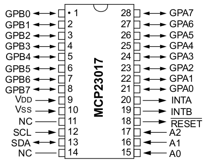
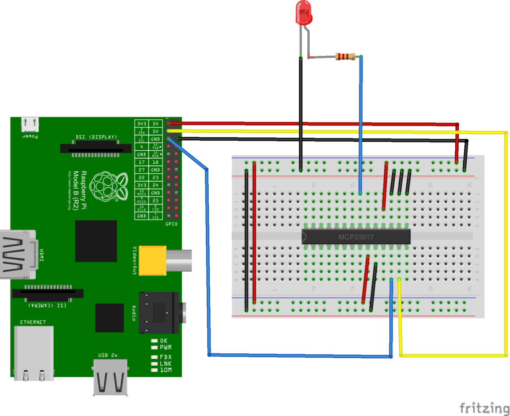
- Pin 9 (VDD) is connected to 3.3V
- Pin 10 (VSS) is connected to Ground
- Pin 12 (SCL) is connected to Pin 5 on the Pi GPIO
- Pin 13 (SDA) is connected to Pin 3 on the Pi GPIO
- Pin 18 (Reset) should be set high so connect this to 3.3V
- Pins 15, 16 & 17 (A0-A2) determine the address of the device. These are tied to ground in our example meaning the address will be 0x20
Here is the pinout of mcp23017
Open a terminal and check the I2C address by typing in sudo i2cdetect – y 1 (raspberry Pi 2). You can see this is 0x20 here
Layout
In this layout we only show 1 led but we connected 8 LEDs to all of the GPA pins
Code
Create a new python file called mcp23017.py and enter the following code
This will count from 1 to 255 and display this as binary on 8 leds
[codesyntax lang=”python”]
import smbus
import time

#bus = smbus.SMBus(0)  #Pi 1 uses 0
bus = smbus.SMBus(1) #Pi 2 uses 1

DEVICE = 0x20 # Device address (A0-A2)
IODIRA = 0x00
OLATA  = 0x14
GPIOA  = 0x12

# Set all GPA pins as outputs
bus.write_byte_data(DEVICE,IODIRA,0x00)

# Set output all 7 output bits to 0
bus.write_byte_data(DEVICE,OLATA,0)

for LedOut in range(1,255):
  # Count from 1 to 255
  bus.write_byte_data(DEVICE,OLATA,LedOut)
  print LedOut
  time.sleep(0.1)

# Set all bits to zero
bus.write_byte_data(DEVICE,OLATA,0)
[/codesyntax]
Run the example by typing
[codesyntax lang=”bash”]
sudo python mcp23017.py
[/codesyntax]
Links
MCP23017-E/SP mcp23017 IC I/O EXPANDER I2C DIP28


