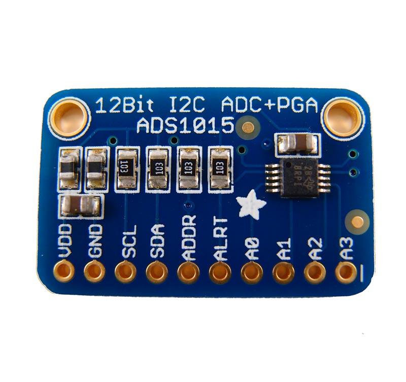
The ADS1015 is a precision analog-to-digital converters (ADCs) with 12 bits of resolution offered in an ultra-small, leadless QFN-10 package or an MSOP-10 package. The ADS1015 are designed with precision, power, and ease of implementation in mind. The ADS1015 features an onboard reference and oscillator. Data are transferred via an I2C-compatible serial interface; four I2C slave addresses can be selected. The ADS1015 operate from a single power supply ranging from 2.0V to 5.5V.
The ADS1015-Q1 device can perform conversions at rates up to 3300 samples per second (SPS). An onboard PGA is available that offers input ranges from the supply to as low as ±256 mV, allowing both large and small signals to be measured with high resolution. The ADS1015-Q1 device also features an input multiplexer (MUX) that provides two differential or four single-ended inputs.
The ADS1015-Q1 device operates either in continuous conversion mode or a single-shot mode that automatically powers down after a conversion and greatly reduces current consumption during idle periods
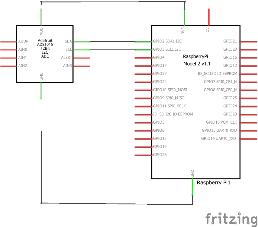
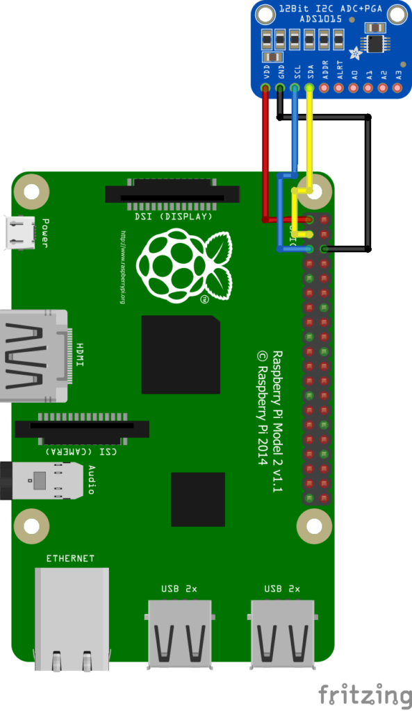
Schematics
Here are some schematics and layout to show you how to connect your ADS1015 module to your Raspberry Pi
Code
In this example you need the Adafruit ADS1015
[codesyntax lang=”bash”]
git clone https://github.com/adafruit/Adafruit_Python_ADS1x15.git
cd Adafruit_Python_ADS1x15
sudo python setup.py install
[/codesyntax]
now type the following
[codesyntax lang=”bash”]
cd examples
[/codesyntax]
Since I have an ADS1015 you have to modify the generic example, open the test example in a text editor, I used geany.
[codesyntax lang=”bash”]
sudo geany simpletest.py
[/codesyntax]
This is the example after I editted it
[codesyntax lang=”python”]
# Simple demo of reading each analog input from the ADS1x15 and printing it to
# the screen.
# Author: Tony DiCola
# License: Public Domain
import time

# Import the ADS1x15 module.
import Adafruit_ADS1x15


# Create an ADS1115 ADC (16-bit) instance.
#adc = Adafruit_ADS1x15.ADS1115()

# Or create an ADS1015 ADC (12-bit) instance.
adc = Adafruit_ADS1x15.ADS1015()

# Note you can change the I2C address from its default (0x48), and/or the I2C
# bus by passing in these optional parameters:
#adc = Adafruit_ADS1x15.ADS1015(address=0x49, busnum=1)

# Choose a gain of 1 for reading voltages from 0 to 4.09V.
# Or pick a different gain to change the range of voltages that are read:
#  - 2/3 = +/-6.144V
#  -   1 = +/-4.096V
#  -   2 = +/-2.048V
#  -   4 = +/-1.024V
#  -   8 = +/-0.512V
#  -  16 = +/-0.256V
# See table 3 in the ADS1015/ADS1115 datasheet for more info on gain.
GAIN = 1

print('Reading ADS1x15 values, press Ctrl-C to quit...')
# Print nice channel column headers.
print('| {0:>6} | {1:>6} | {2:>6} | {3:>6} |'.format(*range(4)))
print('-' * 37)
# Main loop.
while True:
    # Read all the ADC channel values in a list.
    values = [0]*4
    for i in range(4):
        # Read the specified ADC channel using the previously set gain value.
        values[i] = adc.read_adc(i, gain=GAIN)
        # Note you can also pass in an optional data_rate parameter that controls
        # the ADC conversion time (in samples/second). Each chip has a different
        # set of allowed data rate values, see datasheet Table 9 config register
        # DR bit values.
        #values[i] = adc.read_adc(i, gain=GAIN, data_rate=128)
        # Each value will be a 12 or 16 bit signed integer value depending on the
        # ADC (ADS1015 = 12-bit, ADS1115 = 16-bit).
    # Print the ADC values.
    print('| {0:>6} | {1:>6} | {2:>6} | {3:>6} |'.format(*values))
    # Pause for half a second.
    time.sleep(0.5)
[/codesyntax]
Now run the example by typing the following in
[codesyntax lang=”bash”]
sudo python simpletest.py
[/codesyntax]
You should the values of the ADC channels displayed in the terminal window
Links
1pcs ADS1015 ADC ultra-compact 12-precision ADC module development board


